I'm a fan of the phrase "go big or go home" but in this case it became "go home and go big." I was home for the holidays and holding a party. I couldn't bring my new wall visualizer, so I decided to make a new adaptation of it. My original thought was to replace the lights in a Christmas tree with strips of WS2812b LEDs, but I couldn't think of a good way to animate it to react to music. After looking for other places to mount the lights, I figured the best place to put the strips was on the balusters (vertical posts) of the staircase.
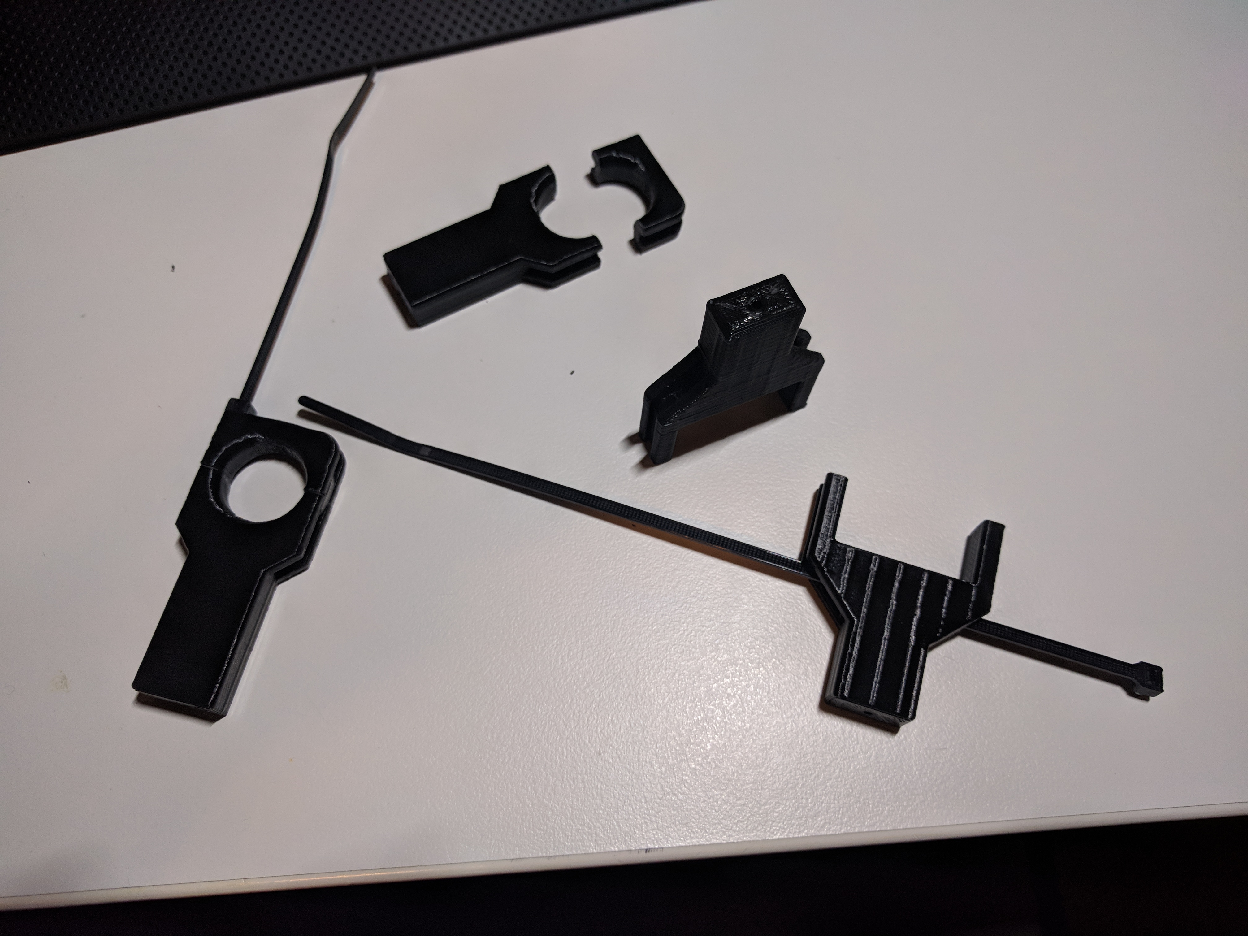
3D printed mounting blocks for LED conduit. These clamp to the staircase balusters using zip-ties.
I found aluminum extrusion designed to hold the LED strips. They come with diffusers and mounting brackets. The mounting brackets are designed to screw into a wall, so I had to make a set of adapters bridge between the mounting brackets and the staircase. I went with a 3D printable design that zip-ties in place. It was important to ensure that these parts wouldn't damage the staircase, since the visualizer would only be installed for a few days before being put in storage for the next party.
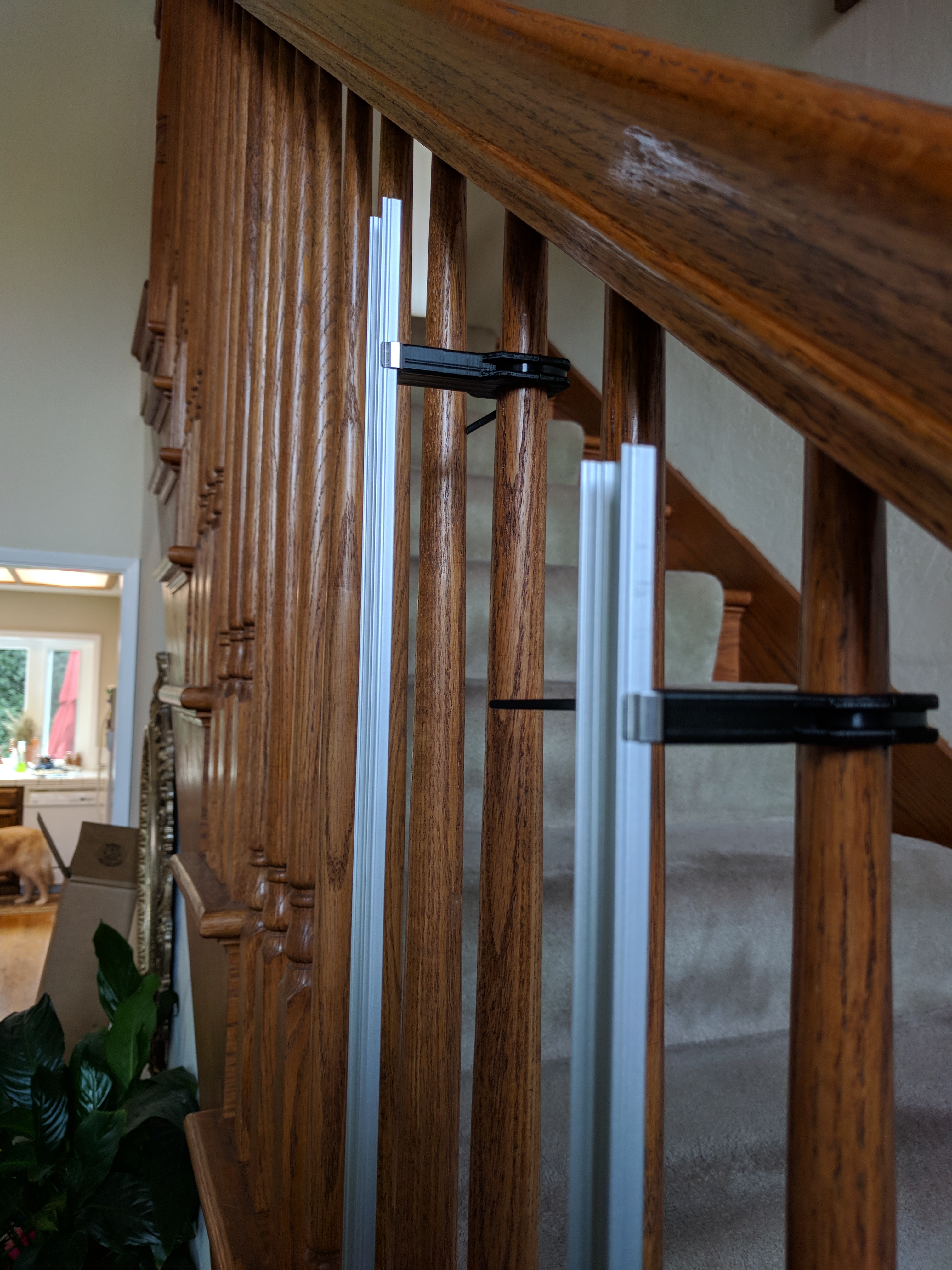
Test fit of aluminum extrusion to the staircase. The 3D printed mounting blocks interface the extrusion brackets to the staircase balusters.
The brackets to mount the aluminum extrusion conveniently clip on. This makes installation of the bars quick and easy. There are no locating features to set the height of the bar. This works out well since the 3D printed mounts sit on a tapered portion of each baluster. The balusters look identical, but they all vary in diameter and taper by a significant amount. The 3d printed parts all sit at slightly different heights. The square brackets for mounting at the bottom of the baluster were designed to be a tighter fit. I checked a select few of the balusters and found them to have nearly identical dimensions for their square sections. I later found I had some selection bias, and not all of the square sections were the same dimension. A number of pieces ended up being press-fits.
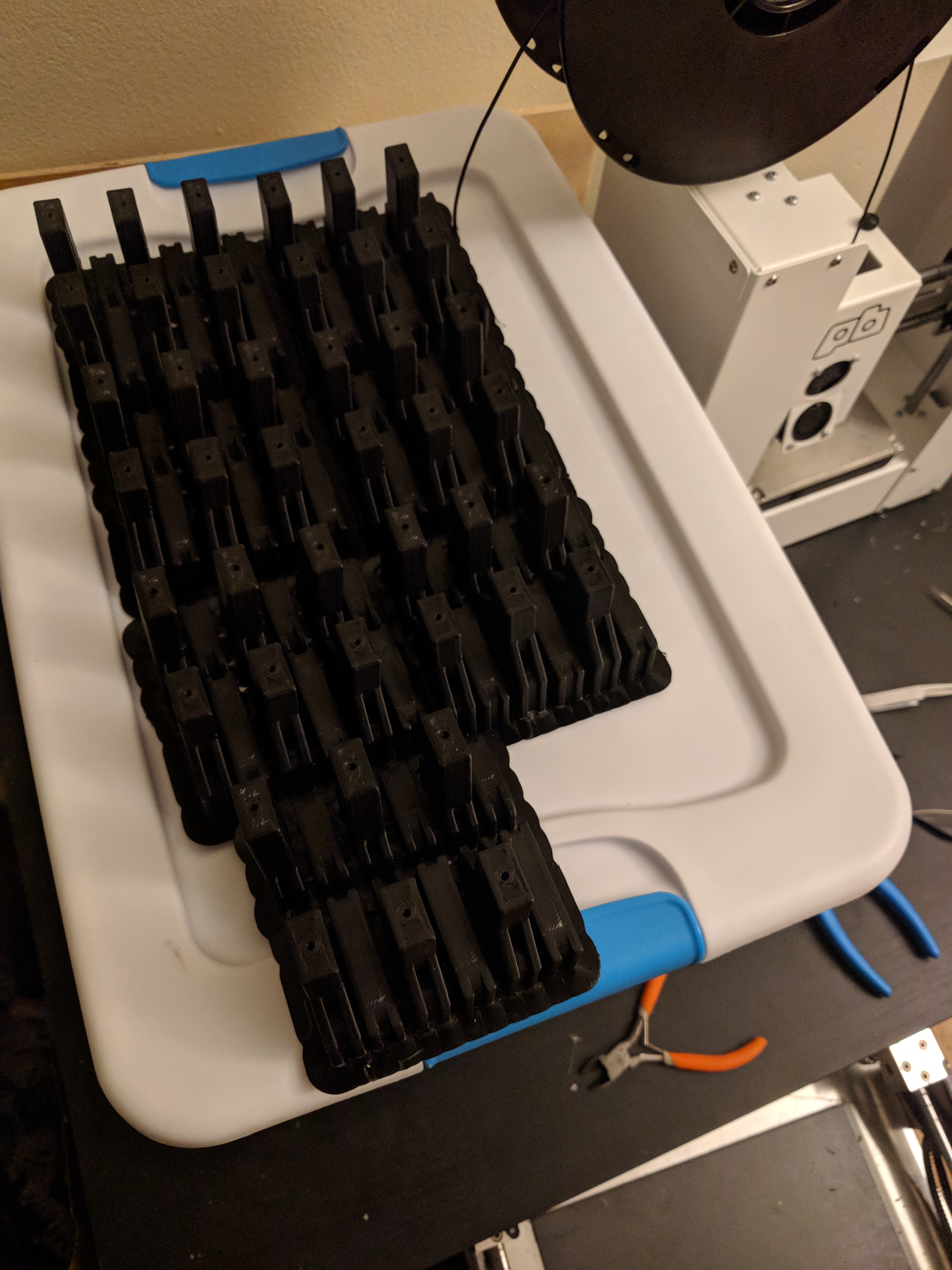
Half of the produced 3D printed brackets. 3 top and 3 bottom brackets were printed at a time until the required 40 brackets were produced.
Production of the 3D printed brackets ended up being a significant challenge due to the massive quantity of parts. I grouped the parts such that I got 3 upper and 3 lower mounts per print, meaning I needed a total of 14 prints to get the parts required to mount 40 LED strips. These were all printed on a heavily used printrbot play. It originally did not work and was sold to me "as-is" and "only good for parts." I stripped it down to parts and built it back up with some attention to detail. I used proper cable sleeving to protect the wiring and it worked fine once reassembled. I replaced the bed with 1/4" aluminum plate because the original 1/8" bed was warped. I suspect the previous owner didn't quite assemble it properly and was plagued by adhesion issues stemming from the warped bed. I just need a thin layer of PVA based glue-stick applied to the bed to get perfect adhesion (sometimes too good) even without elevated bed or chamber temperatures. These prints and another equally massive printing project ended up wearing out the extruder gear and a cooling fan.
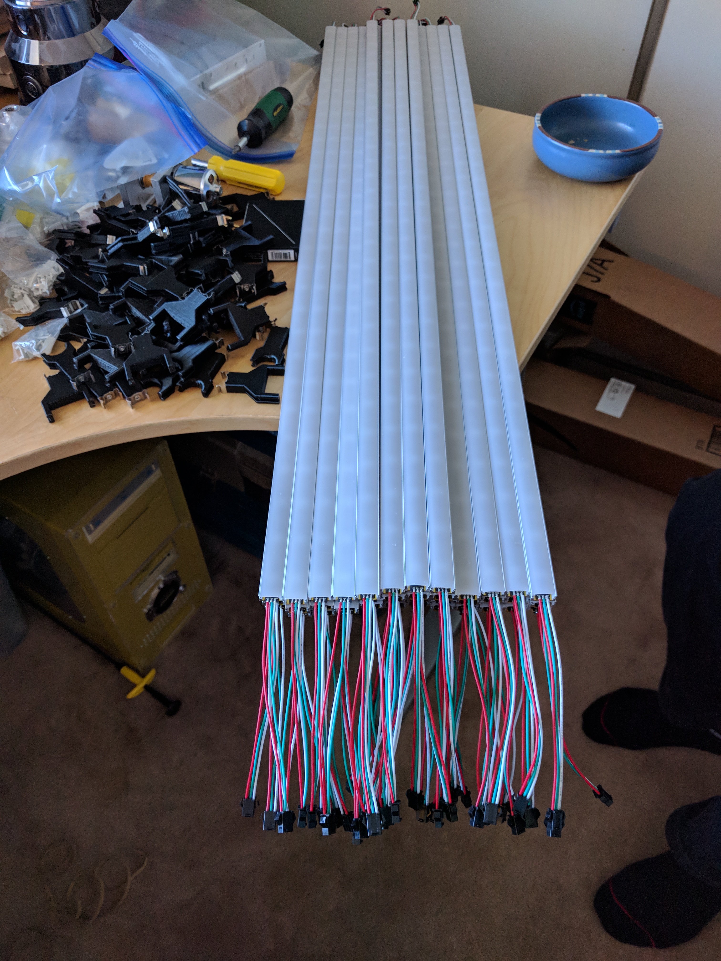
Assembled LED light bars and mounts. Each light bar has a 1M segment of addressable LEDs (30 WS2812b LEDs).
Once again production due to the quantity of components ended up being a significant challenge. Thankfully I have good friends who came over to help with assembly. All of the 3D printed brackets needed metal mounting brackets bolted in place. The LED light bar assembly was surprisingly difficult in large quantity. First, the extrusion needed to be covered in kapton tape. This tape layer ensures that the LED strips can't short to the aluminum. Second, the LED strips had to be adhered to the extrusion (on top of the applied kapton tape). The LED strips come in 5M long rolls. Each roll is built from 10 1/2M segments soldered together. These rolls had to be disassembled into 1M segments before assembling into the aluminum extrusion. Third, connectors needed to be attached to each end of the LED strip. Female connectors were used for the outputs, while male connectors were used for the inputs. Female connections were chose for the outputs because there are always some exposed connections in the array, and the female connectors are harder (nearly impossible) to accidentally short. Finally, a diffuser (came with the aluminum extrusion) was snapped into place. Aside from diffusing the light and hiding the LEDs, the diffuser also acts to protect the LEDs from damage.
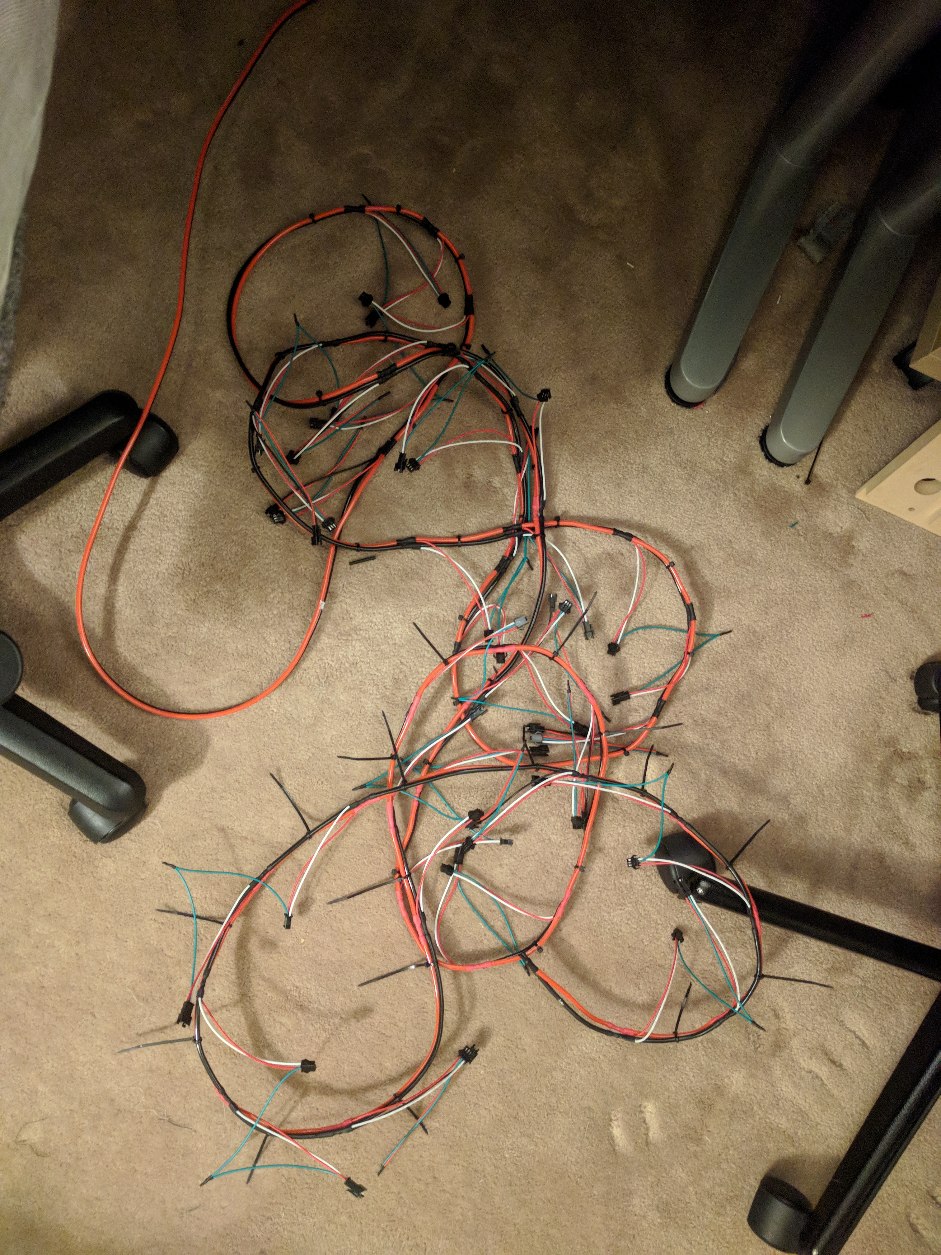
Power backbone for the visualizer. Each strip is connected to the power backbone to ensure minimal voltage drop from the 5V power supply.
Power requirements were a major concern just like the wall mounted visualizer. Every bar has its own connection to a power backbone, which uses thick wire to minimize voltage drop under high current draw. Each LED can draw a maximum current of 60mA. The array consists of 40 bars with 30 LEDs each. This leads to a peak possible current draw of over 70A! This visualizer also uses a Teensy micro controller like my wall visualizer (same code too). The Teensy can support up to 8 channels of WS2812b LEDs, so the visualizer was split into 8 groups of 5 LED bars. A separate set of wires is run to each group of LEDs directly from the Teensy. Running each group in parallel helps to increase data rate and therefore the maximum frame rate of the visualizer. Each channel only needs to drive 150 LEDs, so an 8x increase in frame rate compared to driving all of the LEDs from one channel.
The electronics were mounted in the frame from a 3D printer I had designed but never finished making. I used a slightly higher end power supply than the one in my wall mounted visualizer (supposedly UL rated). The wall power is fused with a power switch. RJ45 connectors were used for the signal lines, and an XT60 was used for the power backbone. This makes it possible to quickly disconnect the electronics for storage. The final visualizer turned out very well. The visualizer was animated using the same code from my wall visualizer with a few modifications. First, there is no left/right channel mirroring in this visualizer. Lower frequencies are at the base of the staircase and higher frequenncies are at the top. An additional animation was added (used for a Christmas party) where icicles would grow and drop pieces depending on the amplitude at each frequency. I plan to add more animations for other events (fireworks / countdown for new years).
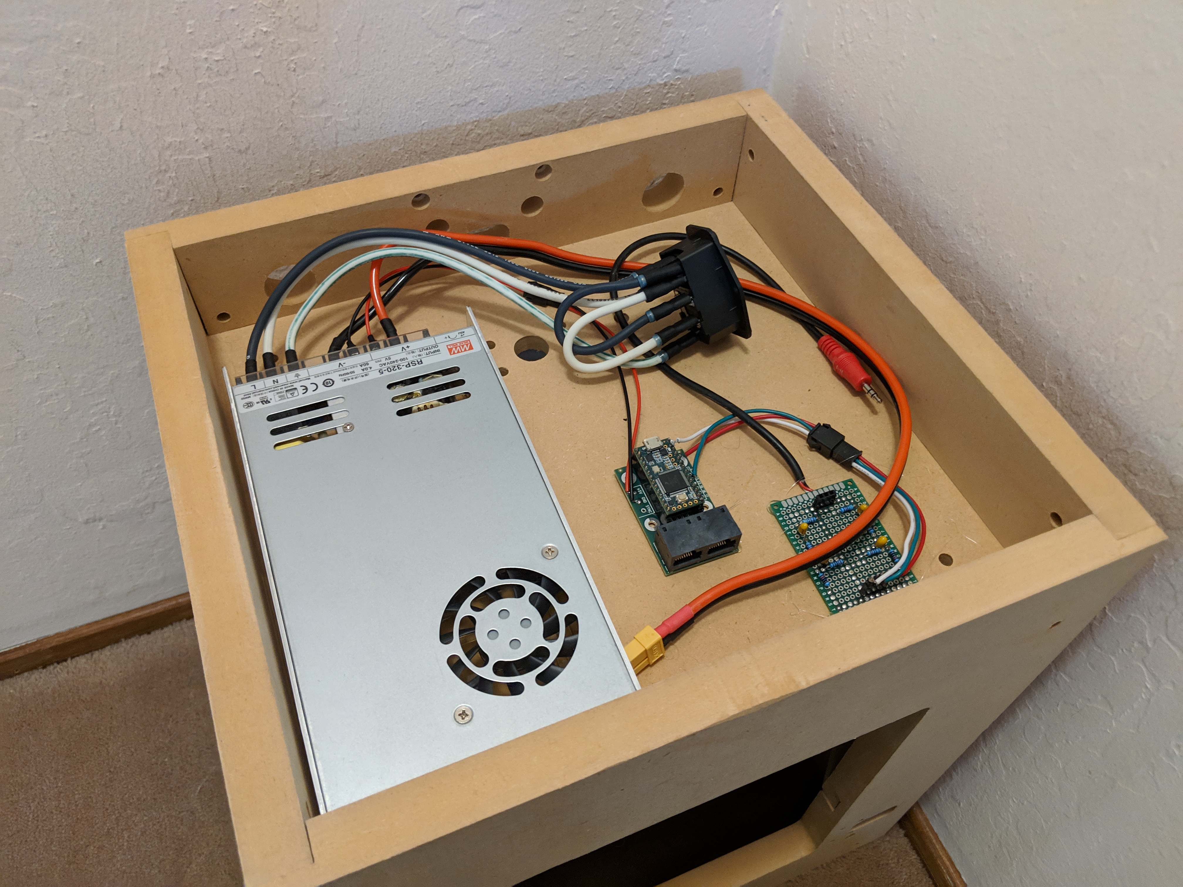
Power supply and micro controller for the visualizer. The components were mounted in the unused frame from a 3D printer I was building.
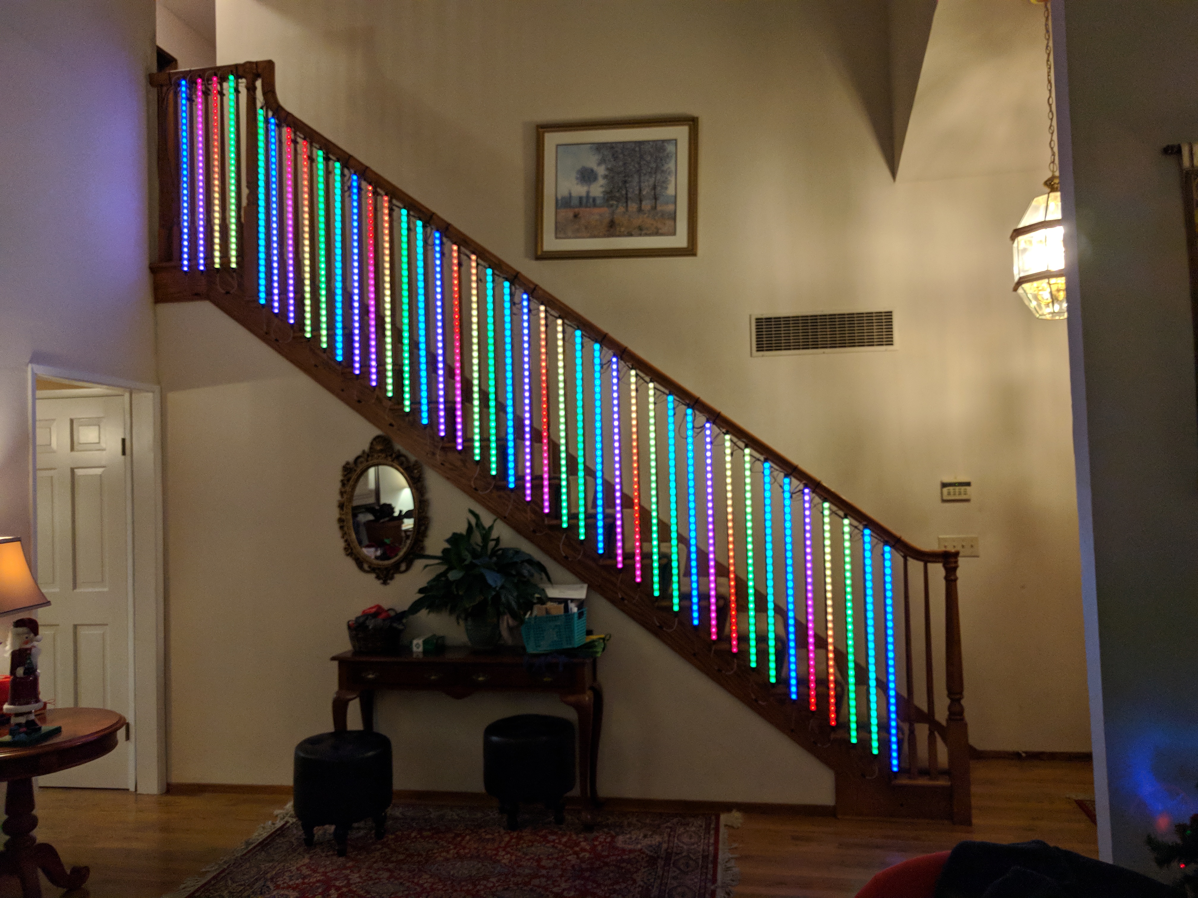
Completed visualizer assembly. All LEDs were lit with a rainbow pattern to verify everything was working.
Rainbow Fourier animation. This visualizer mode is the same one used in my wall mounted visualizer.
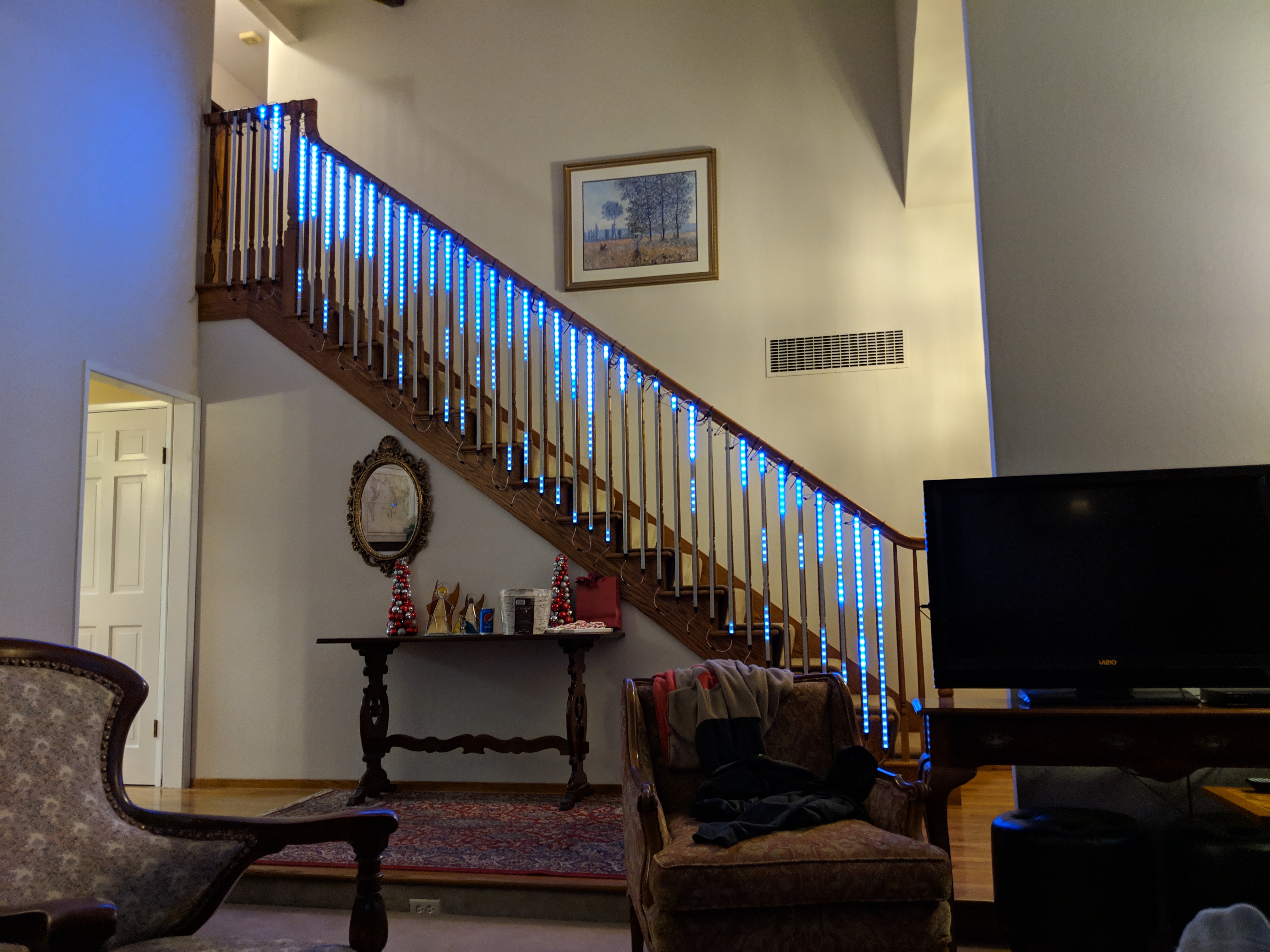
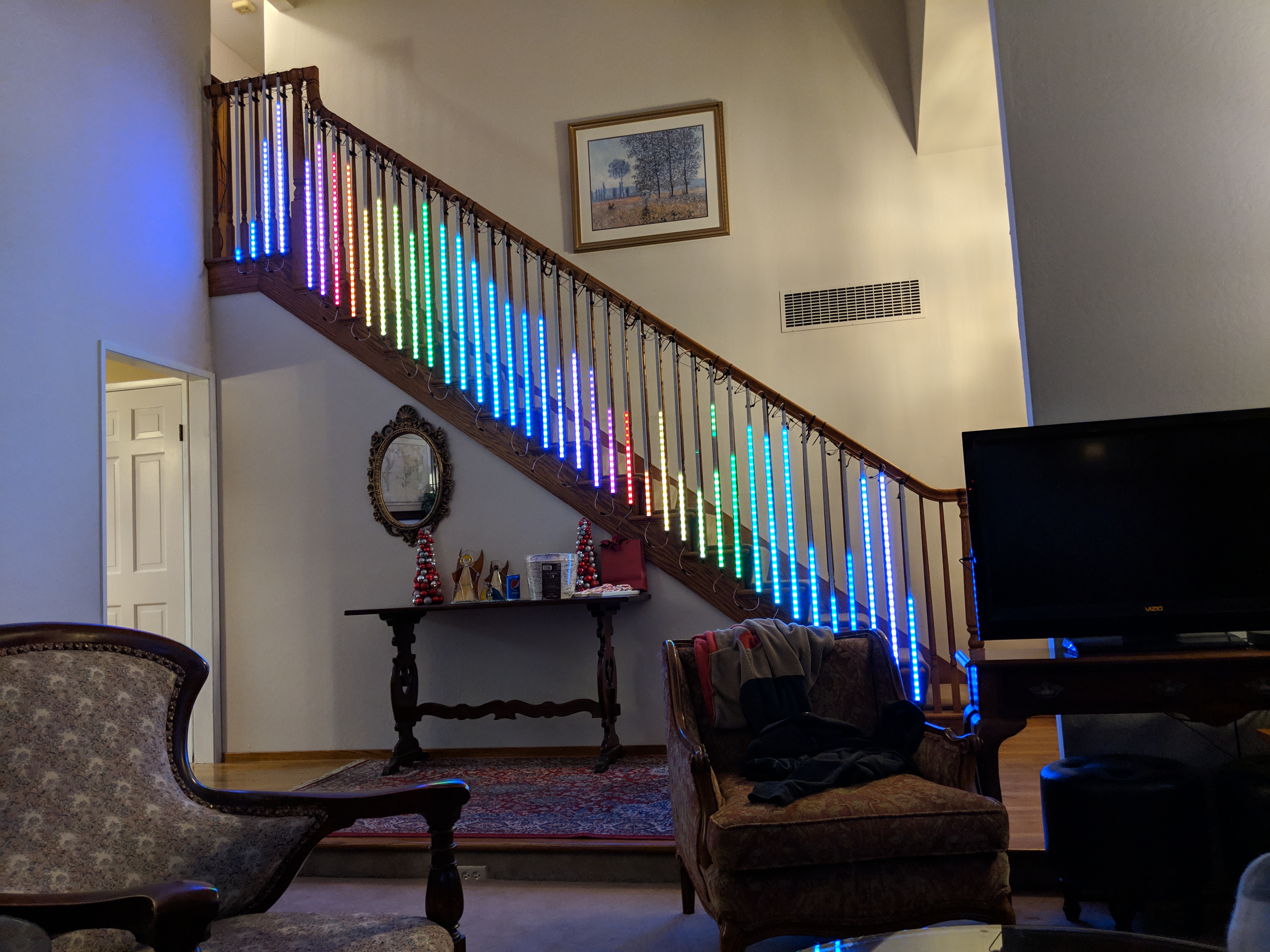
Icicle Fourier animation. Icicles grow with increasing frequency bin content and drop a piece when quickly losing content.