*** I'm still in the process of writing up my work on this project, so things like oscilloscope measurements of the phase waveforms, and tuned servo plots will be added soon. ***
I've been meaning to revisit a custom built brushless motor controller for a while, but haven't gotten around to it until recently. The LED Watch as well as some grad-school projects helped me build confidence in working with SMD components. To somewhat reiterate my motivations for this project... Brushless motors (specifically the large RC hobby brushless motors) offer higher torque, higher power (better heat-sinking), and better lifetime than their brushed counterparts at a fraction of the price. I have a number of projects in mind that need precise high-power servo motors, but there aren't many affordable motor controllers that can use large hobby brushless motors as servos.
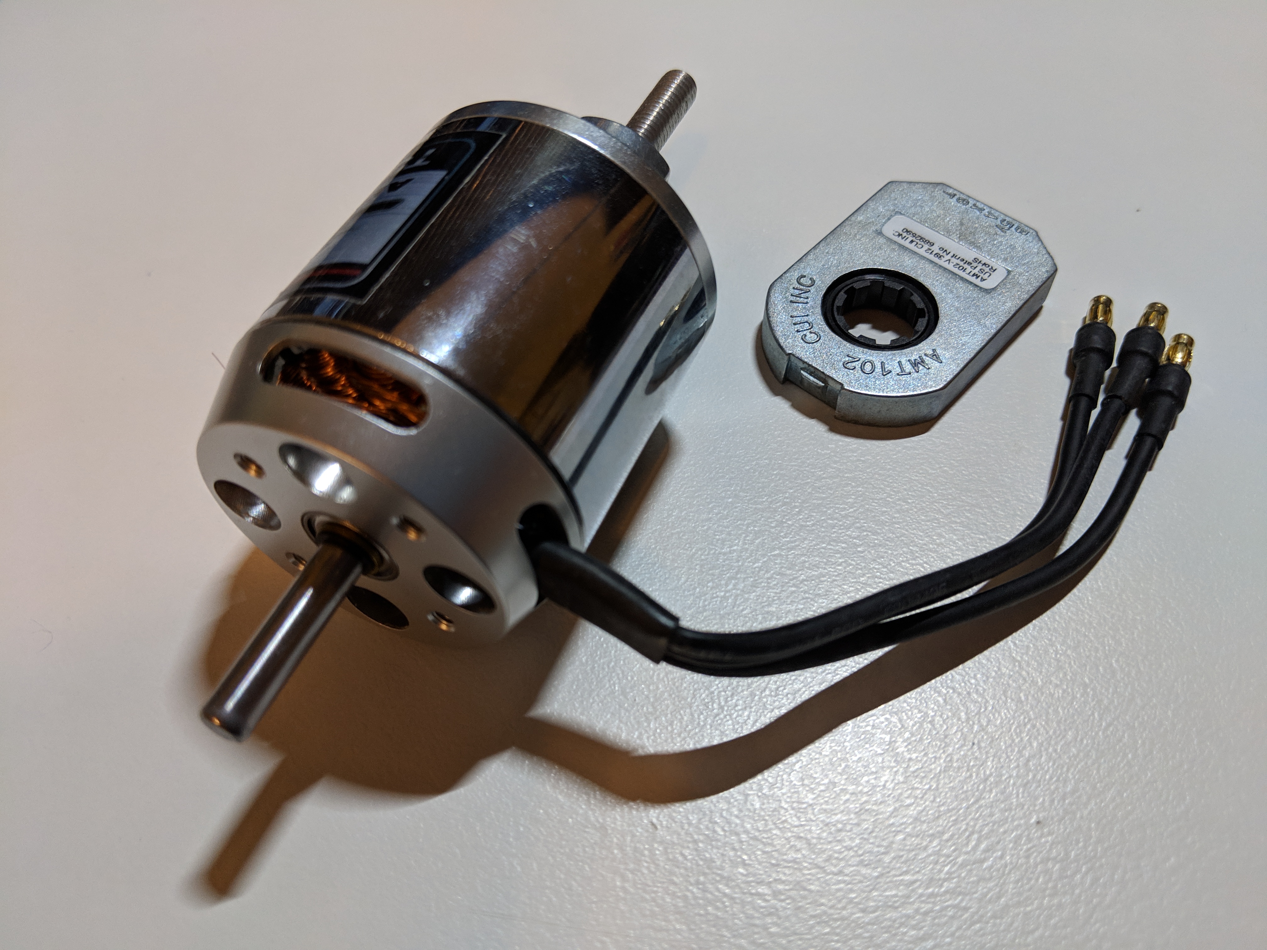
Hobby brushless motor and quadrature encoder. These are the same motor and encoder combination from the 3D printer I had partially built a few years ago.
I started this motor controller project by picking some design constraints for the controller like supply voltage, motor amperage, sensor inputs, and communication methods. The first constraints I set were the inputs. I wanted to try a wide range motor commutation methods that could be removed to reduce cost in a future version of the controller. Brushless motor controllers need to know the position of the rotor (magnets) relative to the stator (coils). Cheap RC brushless motor controllers are almost universally sensorless - meaning they don't use any form of position sensor to determine motor position, instead they estimate it from the motors back EMF. This requires measuring the voltage on each phase of the motor. Sensored brushless motor controllers typically use hall effect sensors that directly sense the position of the magnets. A less commonly used method is measuring motor position by encoder. This method is used less often because the encoder must be aligned to the magnets through software calibration. I also wanted to implement field oriented control (FOC) - the most efficient way to drive a brushless motor - which requires current measurements for each phase. Supply voltage and motor amperage constraints were pretty open, so I ended up setting the constraints around the components I chose for the controller. For communication I picked CAN and RS232. CAN is designed to work in harsh environments (automobile) and multiple devices can be connected to the same bus, keeping wiring simple and clean. RS232 is easy to implement and has USB adapters, making interfacing with a computer easy.

Motor controller power and signal board layouts. The logic board is four layers while the power board is only two layers.
I designed the PCBs in Kicad, since I was so happy with its workflow on the LED Watch. Thick copper is necessary for power traces to reduce resistive heating in the motor controller under high loads. Unfortunately, thicker copper also limits the resolution of the PCB traces. I was forced to split the power components and logic into separate boards to keep PCB costs low, improve signal noise, and get thicker copper for the power circuit. Only the FETs and a temperature sensor are on the lower power board. The microcontroller, gate driver, and sensing circuitry are on the logic board. A key design element of the power board is heatsinking through the bottom of the PCB. Large groups of vias stitch top and bottom copper layers together, which provide a low resistance path for heat to sink from the FETs to the back of the PCB. I will eventually add a heatsink that presses against the bottom layer of copper to get heat out of the board as effectively as possible. The logic board needed to be four layers to properly isolate signals. A ground plane (layer 2) was included to shield any component (layer 1) from routing traces (layers 3 and 4).
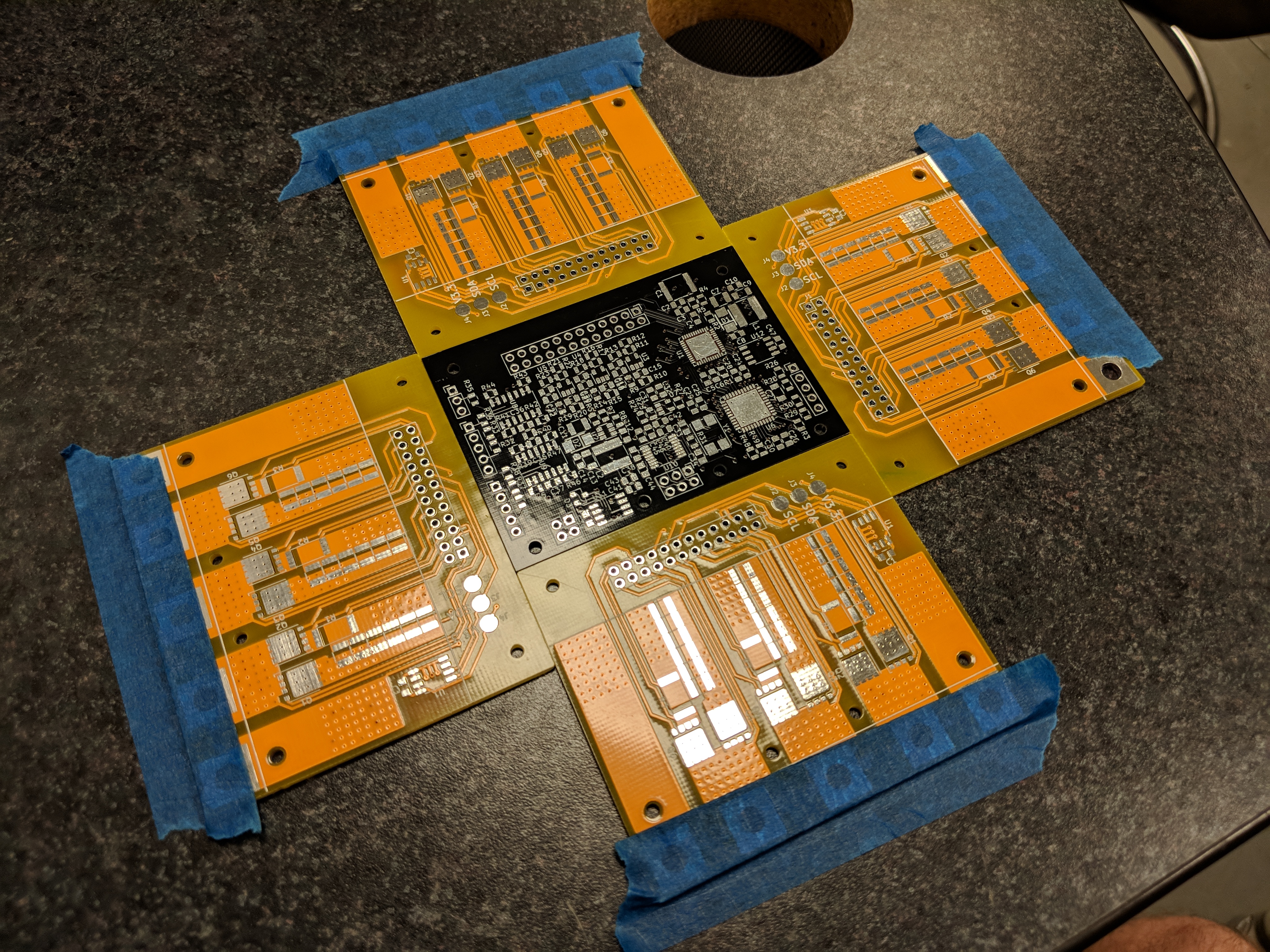
Solder paste application on the logic board. The board was held in place by a set of power boards taped to the table. These boards also provide a level surface for the stencil to lay on while applying solder paste.
Soldering of the two boards was easy thanks to the stencils I ordered with the PCBs. I was able to use extra PCBs to hold the PCB in place while applying the solder paste. Each component was placed by hand with a set of tweezers under a USB microscope. The smallest SMD components were 0804, so it was easy to handle. I was less concerned with size and packaging, and more concerned with ease of assembly and debugging (contrasting the 0402 components used in my LED Watch). Soldering was completed with a mix of oven and heat gun. The heatgun was mostly used for rework to fix bridged pins on the QFN packages used for the microcontroller and gate driver chips. Rework was accomplished by applying flux with a flux pen and swiping a fine tipped soldering iron across the sides of the QFN. There are numerous tutorials online showing how to fix these bridged pins. Any through hole components (pin headers) were mounted by hand and soldered manually in place.
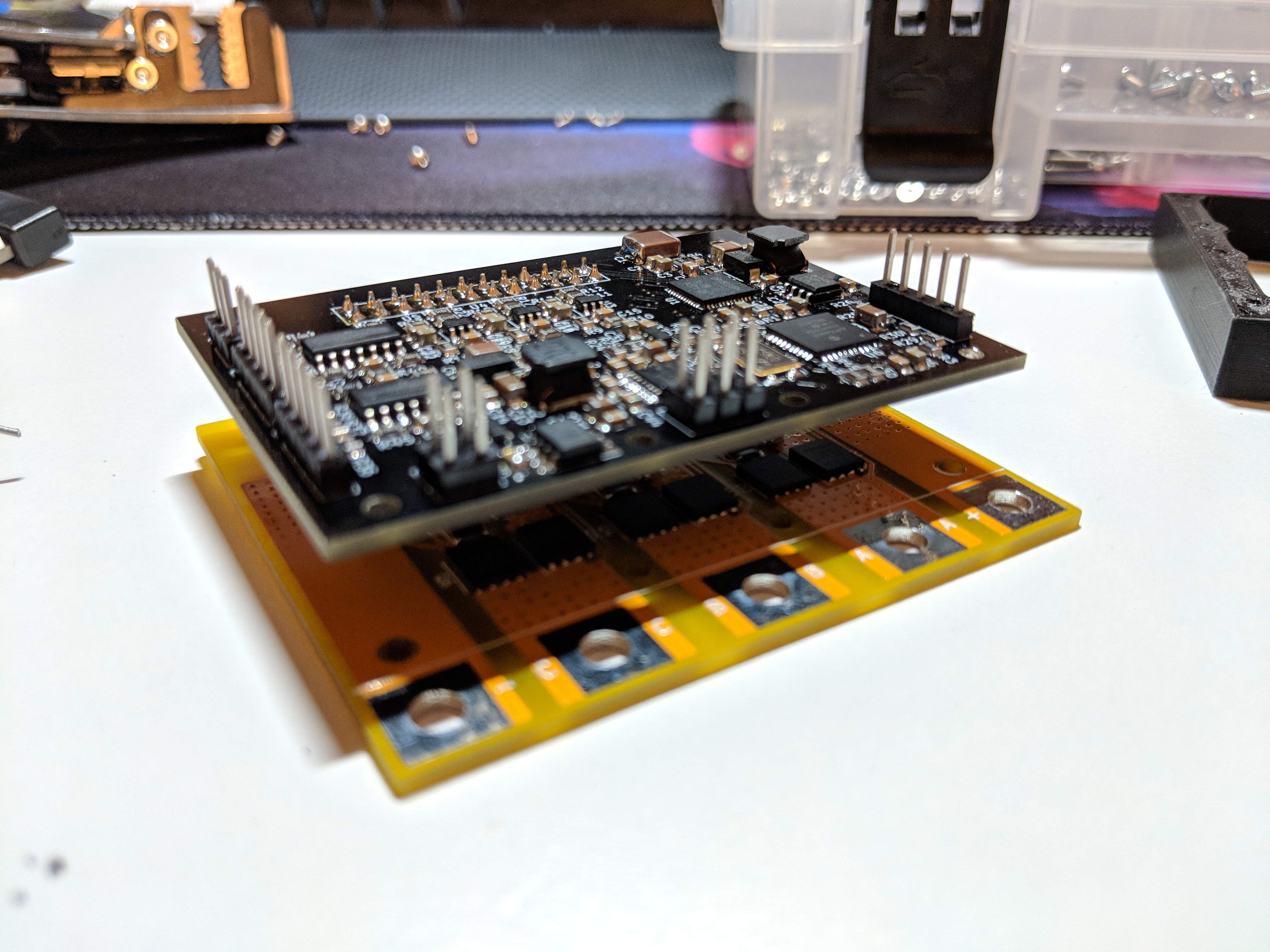
Motor controller signal and power boards mounted together. A 3D printed ring is later used space the boards from eachother and protect the power FETS from external debris (metal particles, dust, etc...)
The final board assembly went smoothly and the boards passed the smoke test! I color coded the PCBs to really illustrate the differences between them. The yellow board is the power board (yellow and electricity always go together), and the black board is for logic (looks cooler). The powerboard has large mounting pads to screw ring terminals directly to the board. The outer pads are input power and ground (poor choice, which I'll explain later), and the center are the A, B, and C output phases for the motor. The power board also sticks out more than the logic board, to make attaching power lines easier once the case is added.
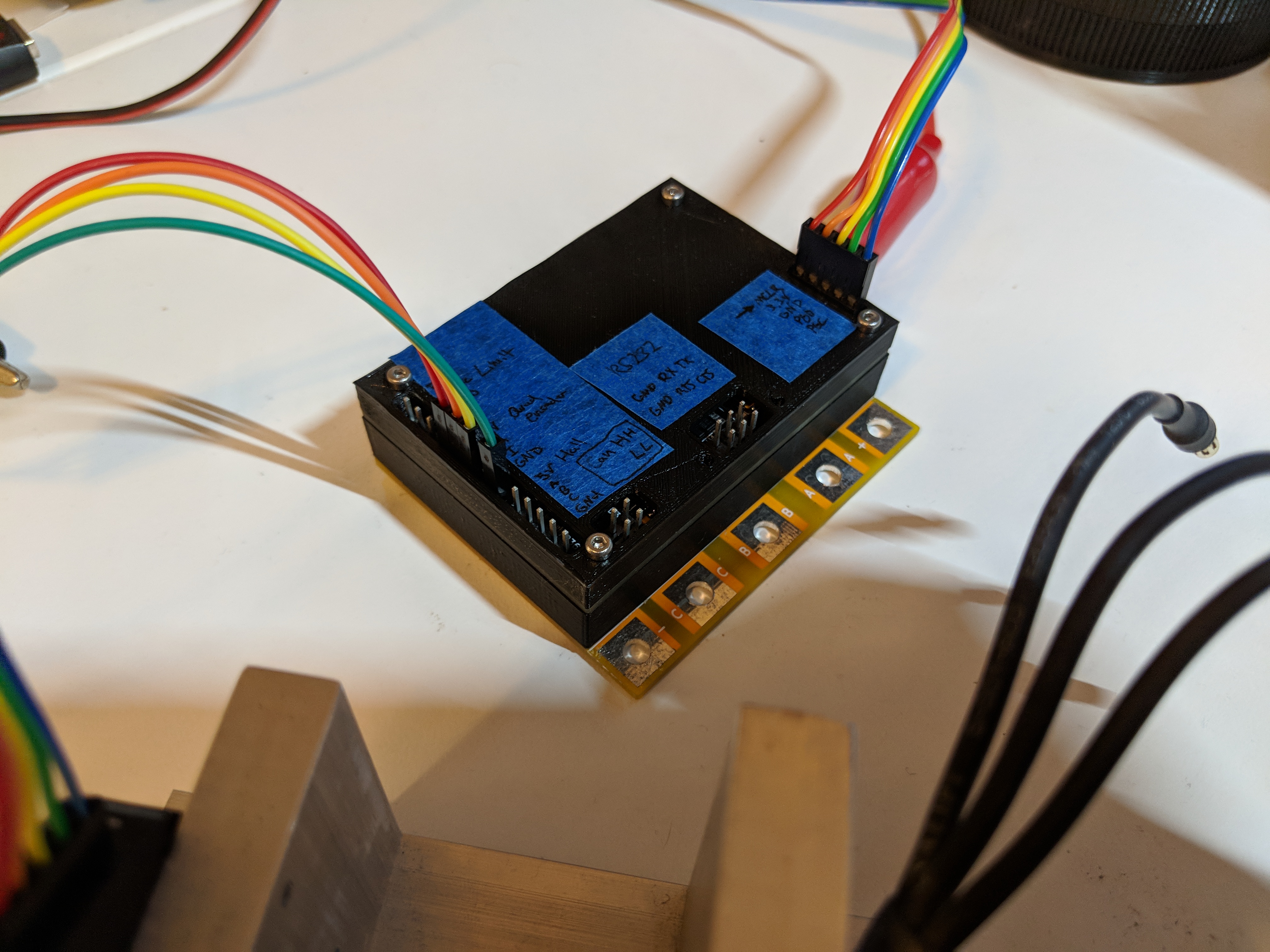
Fully enclosed motor controller with labels. The casing helps prevent accidental shorts from debris (or me poking around with the oscilloscope).
I 3D printed a case to protect the electronics from shorting in operation. It makes the controller look more like a product than a hobby project. I still need to machine the aluminum heatsink for the bottom of the power board. The top cover also includes a set of labels remind me where to plug in the various cables. The right side of the controller has one header for the in circuit programmer and debugger (PICkit3). This port makes developing code for the controller much easier as the program can be paused at arbitrary lines of code and individual registers can be read. The left side of the board has various sensor inputs (quadrature encoder, hall effect, and limit switch). The center has RS232 serial and CAN bus connections. Headers were used to save space compared to common connectors like DB9 or RJ45 for the serial and CAN interfaces respectively.